RF Ceramic Chip Inductors
High frequency multi-layer chip inductors feature a monolithic body made of low loss ceramic and high conductivity metal electrodes to achieve optimal high frequency performance. These RF chip inductors are compact in size and feature lead-free tin plated nickel barrier terminations and tape and reel packaging which makes them ideal for small size/high volume wireless applications.
Applications:
- CELL/PCS Modules
- Wireless LAN
- Broadband Components
- RFID
- RF transceivers
- RoHS Compliant (Standard, "V" Code)
- Sn/Pb Terminations Optional ("T" Code)
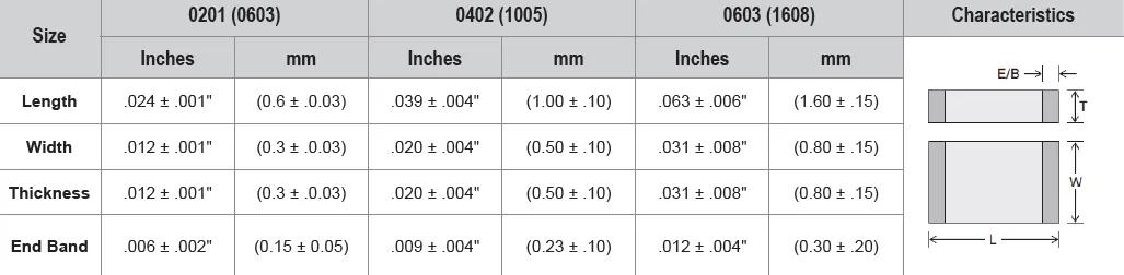
| EIA Size (mm) | L RANGE | Q FACTOR (Min.) | SRF(Typ.) | TEMPERATURE |
|---|---|---|---|---|
| 0201 (0603) | 0.6 - 39 nH | 4 (100 MHz) | >21 GHz (1.0 nH) | -55°C to + 100°C |
| 0402 (1005) | 1.0 - 120 nH | 8 (100 Mhz) | >21 GHz (1.0 nH) | -55°C to + 100°C |
| 0603 (1608) | 1.2 - 220 nH | 12 (1 MHz) | >23 GHz (1.0 nH) | -55°C to + 100°C |
Inductance Range / Electrical Characteristics
| EIA Size \ Inductor Value |
0201 |
0402 |
0603 |
||
| Inductance | |||||
| nH | Code | Tolerance | |||
| 0.6 | 0N6 | C S |
300 mA | ||
| 0.7 | 0N7 | 300 mA | |||
| 0.8 | 0N8 | 300 mA | |||
| 0.9 | 0N9 | 300 mA | |||
| 1.0 | 1N0 | 300 mA | 300 mA | 300 mA (S only) | |
| 1.2 | 1N2 | 300 mA | 300 mA (S only) | 300 mA (S only) | |
| 1.3 | 1N3 | 300 mA | |||
| 1.5 | 1N5 | 300 mA | 300 mA (S only) | 300 mA (S only) | |
| 1.8 | 1N8 | 300 mA | 300 mA (S only) | 300 mA (S only) | |
| 1.9 | 1N9 | 300 mA | 300 mA (S only) | ||
| 2.0 | 2N0 | 300 mA | 300 mA (S only) | ||
| 2.2 | 2N2 | 300 mA | 300 mA (S only) | 300 mA (S only) | |
| 2.3 | 2N3 | 300 mA | |||
| 2.4 | 2N4 | 300 mA | 300 mA (S only) | ||
| 2.5 | 2N5 | 300 mA | |||
| 2.7 | 2N7 | 300 mA | 300 mA (S only) | 300 mA (S only) | |
| 3.0 | 3N0 | 300 mA | 300 mA (S only) | ||
| 3.3 | 3N3 | K S |
300 mA | 300 mA | 300 mA |
| 3.6 | 3N6 | 300 mA | 300 mA | ||
| 3.7 | 3N7 | 300 mA | 300 mA | ||
| 3.9 | 3N9 | 300 mA | 300 mA | 300 mA | |
| 4.3 | 4N3 | 300 mA | |||
| 4.7 | 4N7 | 300 mA | 300 mA | 300 mA | |
| 5.1 | 5N1 | 300 mA | 300 mA | ||
| 5.6 | 5N6 | 300 mA | 300 mA | 300 mA | |
| 6.2 | 6N2 | 300 mA | |||
| 6.8 | 6N8 | J K |
250 mA | 250 mA | 300 mA |
| 7.5 | 7N5 | 250 mA | |||
| 8.2 | 8N2 | 250 mA | 250 mA | 300 mA | |
| 10 | 10N | 250 mA | 250 mA | 300 mA | |
| 12 | 12N | 250 mA | 250 mA | 300 mA | |
| 13 | 13N | 250 mA | 250 mA | 300 mA | |
| 15 | 15N | 250 mA | 250 mA | ||
| 18 | 18N | 200 mA | 200 mA | 300 mA | |
| 20 | 20N | 200 mA | 200 mA | ||
| 22 | 22N | 200 mA | 200 mA | 300 mA | |
| 23 | 23N | 200 mA | |||
| 27 | 27N | 200 mA | 200 mA | 300 mA | |
| 33 | 33N | 200 mA | 200 mA | 300 mA | |
| 39 | 39N | 200 mA | 150 mA | 300 mA | |
| 43 | 43N | 150 mA | |||
| 47 | 47N | 150 mA | 300 mA | ||
| 56 | 56N | 150 mA | 300 mA | ||
| 68 | 68N | 100 mA | 300 mA | ||
| 82 | 82N | 100 mA | 300 mA | ||
| 100 | R10 | 100 mA | 300 mA | ||
| 120 | R12 | 100 mA | 300 mA | ||
| 150 | R15 | 300 mA | |||
| 180 | R18 | 300 mA | |||
| 220 | R22 | 300 mA | |||
| 270 | R27 | ||||
| 330 | R33 | ||||
| 390 | R39 | ||||
| 420 | R42 | ||||
| 560 | R56 | ||||
| 680 | R68 | ||||
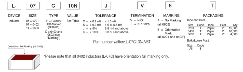
Example Part Number: LRC0402CC1N0GV001B
Description: Ceramic Inductor, 0402, 1.0nH±0.2nH, 300mA, Ni/Sn (RoHS), Orientation Mark Full Marking, Bulk

How to Order
Valid options are shown except for Capacitance
A typical PN is LRC0201CC10NGVZZZT. This part number breaks down as follows:
New Johanson Global Part Number Breakdown
* Not all combinations create valid part numbers, ask our Apps Engineering Team for assistance creating a valid part number Request for assistanceClick below to see the new Global Part Number Reference Chart for this product
Johanson has instituted a new Global Part Numbering (GPN) system.
Only the part number is changing. The parts are produced with the exact same materials, manufacturing processes, manufacturing controls, dimensions, physical attributes and testing as the parts supplied with the legacy part numbers.
The GPNs will be phased in over the next several years and are planned to be completed by January 1, 2026.
We will continue to quote and accept orders with the current (legacy) part numbers throughout this period.
Beginning January 1, 2022, all samples will be provided with the GPN.
Updates associated with this change will occur periodically.
A database for the approximate 2 million crosses can be accessed at: https://www.johansontechnology.com/pn-search