SRF & PRF for RF Capacitors
Capacitors exhibit both series and parallel resonant frequencies. There is a frequency for a capacitor with a given physical size/construction and a given capacitance value at which the component looks like an inductive impedance. Indeed, above this frequency one can have essentially a "DC blocking inductor". This frequency is called the Series Resonant Frequency (SRF). The magnitude of the transmission impedance the capacitor presents will be extremely low from the bottom frequency end determined by the capacitance value, right through the SRF until one approaches the first Parallel Resonant Frequency (PRF). The first PRF is frequently called simply the PRF, although in reality there is a second PRF, third PRF, and so on. A rough rule of thumb puts the PRF at twice the frequency as the SRF. The magnitude of the transmission impedance dip differs significantly at each PRF frequency, and with the various values of capacitors.
Exactly at the SRF, one will have the lowest possible impedance, and therefore, a capacitor is commonly used for narrow band RF bypass applications by choosing a capacitor whose SRF is at the required bypass frequency. In other words, at the SRF, the capacitive impedance of the device equals the parasitic inductive impedance of the device. The user is only left with the ESR (no reactive component) at that frequency.
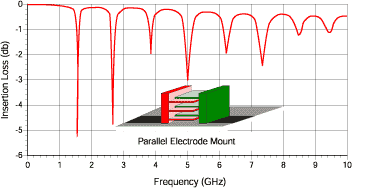
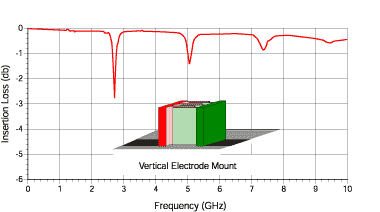
For applications where low impedance is desired, but it is unimportant if the capacitor looks either capacitive or inductive, a capacitor could be used up to a frequency close to the PRF. Above the SRF, the user essentially has a "DC blocking inductor". At the PRF, the transmission impedance goes relatively high, and the capacitor is virtually useless around this frequency. There is an industry "trick" to effectively extend the usable frequency range in this application. That is to mount the capacitor in a vertical position so that the capacitor terminations both still meet the pads where it’s mounted, and so the width of the capacitor is now effectively the height. Doing this will eliminate all odd-order PRFs including the first PRF.

(Figure A)
Figure A (above) illustrates normal mounting where the electrodes are parallel to the substrate surface and the electrical effect for a given capacitor value. Figure B (below) illustrates vertical mounting where the electrodes are perpendicular to the substrate surface and the electrical effect for the same given capacitor value.

(Figure B)
The PRF effects are due to very complex mechanisms related to the different phase paths to the various electrodes of the multi-layer capacitor. At JTI, we typically measure the S-parameters in a normal orientation (per Figure A) showing the first PRF, allowing the user to optionally mount it vertically which will eliminate the first PRF.
Of course, for matching applications, it is extremely important as to whether the component looks like a capacitor or an inductor. In this application, a designer will almost always want to be well below the SRF of the capacitor. We can say that, for example, a 10pF capacitor could look like a 1000pF capacitor as the SRF is approached.

See Figure C for Johanson Technology’s SPICE equivalent circuit for a capacitor. The values shown are for a typical 10 pF capacitor at 900 MHz. This model tends to give a better SPICE simulation than the more common model where Cs represents the essential C at low frequencies, and Cp (if a Cp is even in the model) represents a fraction of Cs, even though this more common model is more conceptually easy to understand. Keep in mind that even our improved model’s accuracy is not ideal at RF frequencies because the elements of this model themselves have a given dependence on frequency. In our model, at low frequencies, the parallel equivalent of Cs and Cp give the essential capacitance. Cs and Ls in our model are what give us the SRF effect. The network of Ls in series with Cs; which is in parallel with Cp is what gives us the first PRF effect. Note also that our model (and the common model) has no provision for simulating a second PRF. Rp is in our model for a more accurate simulation of what the capacitor looks like at RF frequencies, so don’t put an ohmmeter across a capacitor looking for Rp at DC where the Insulation Resistance will be typically greater than 10,000 Ohms! This model (as well as a more "traditional" model) is reflected in our MLCSoft® SPICE simulation software which is available on CD-ROM or from our web page.
IMPORTANT NOTE: Our value for Ls, when using the improved JTI model, may seem slightly (about 50%) higher than a competitor’s advertised Ls because of the modeling difference noted above. Be cautious not to compare Ls directly without realizing the difference in modeling.
Additional Resources:
Understanding Chip Capacitors: Use this technical booklet to learn about Q factor, ESR, and RF capacitor behavior, plus how precise measurements impact RF and microwave circuit designs.