2450BM14A0002 Matched Balun for TI 253X Family Chipsets
Johanson Technology, Inc. 2450BM14A0002 Matched Balun for the Nordic nRF24L01/nRF24L01+ Chipsets
November 2009
1. Introduction
The nRF24L01/nRF24L01+ from Nordic Semiconductor is a 2.45GHz one chip, ultra low power transceiver.
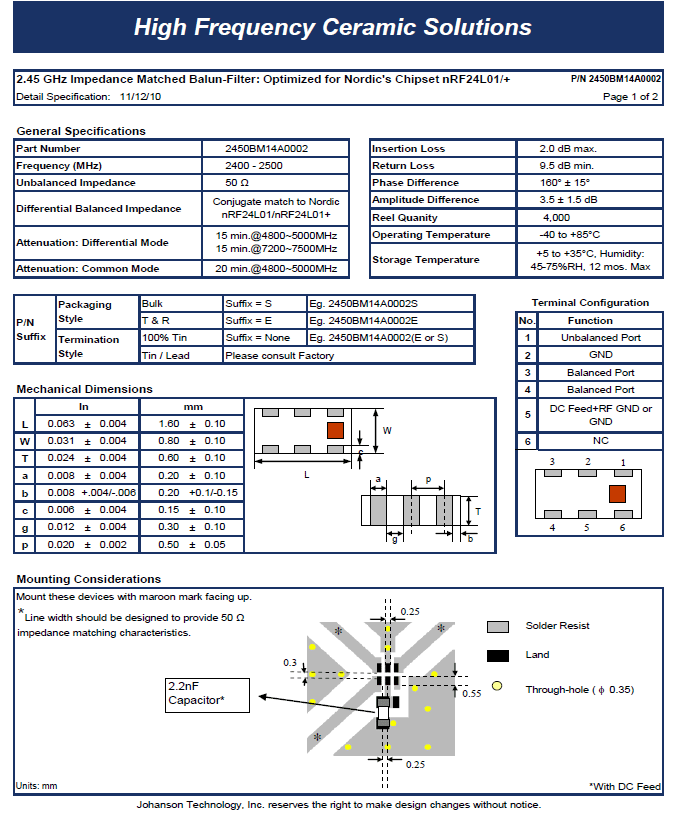
Johanson Technology’s, 2450BM14A0002 LPF-Balun was specifically designed for use with the nRF24L01/nRF24L01+ chipsets. This matched balun greatly simplifies the RF front-end by considerably reducing component count, system variability, implementation size area, and PCB sensitivity.
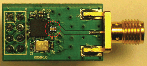
Figure 1. Component picture.
The 2450BM14A0002 is an SMD six-pin LTCC device with a small foot print of only 1.6 mm x 0.8 mm (EIA 0603).
2. Description of the Reference Design
Johanson Technology has developed a solution with a chip Balun-Harmonic filter integrated passive component that is especially matched for the nRF24L01/nRF24L01+ ICs, the 2450BM15A0002, shown in Figure 1.
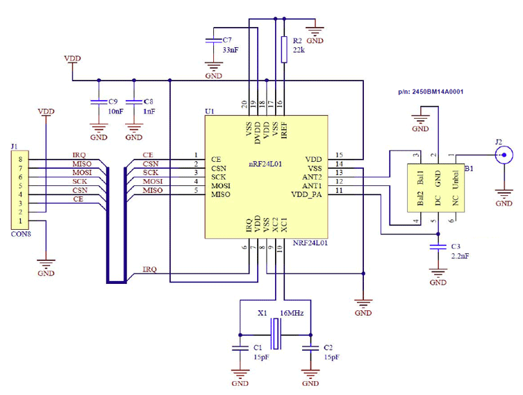
Figure 2. Integrated Reference Design
The rightmost is the JTI matched balun 2450BM14A0002.
Please refer to Appendix A for the datasheet of the balun filter component.
The traditional reference design for RF balun has been the discrete solution shown in Figure 2.
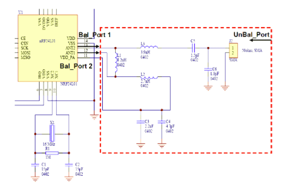
Figure 2. Discrete Reference Design
3. Layout
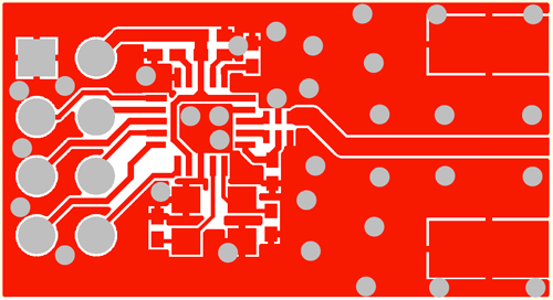
Figure 3. Layer 1 of the Reference Design Layout
In the event that the reference design can not be copied, then the routing from the RF pins ANT1 and ANT2 must be symmetrical to the matched balun component, 2450BM14A0002. The length of the tracks should be kept to a minimum and preferably the same length and width that are used in the reference design. If this routing is not symmetrical, then the output power may be reduced and the harmonics may increase.
The component placement influences the RF performance. It is recommended that the reference PCB layout be copied as closely as possible. In particular, the designer should make note of all dimensions between the nRF24L01/nRF24L01+ and 2450BM14A0002.
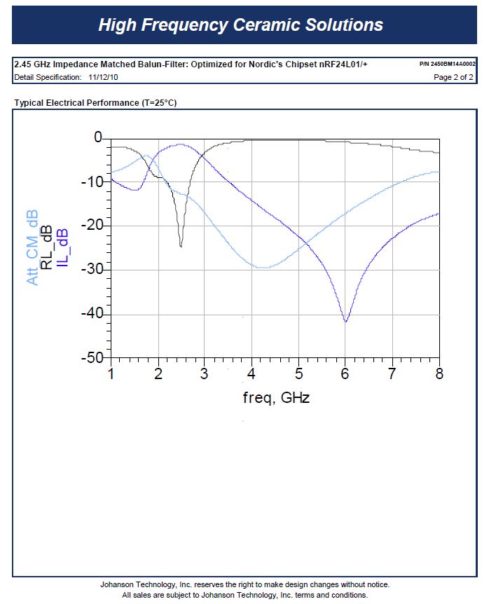
4. Measurement Results
All results presented in this chapter are based on measurements performed with nRF24L01/nRF24L01+ and 2450BM14A0002 Reference Design board. All measurement results presented are the average of each batch tested from typical devices.
Johanson’s 2450BM14A0002 Harmonic Filter - Balun offers improved suppressed 2nd and 3rd harmonics, it eases implementation and increases margin to FCC/ETSI compliance when compared to solution with discrete passives.
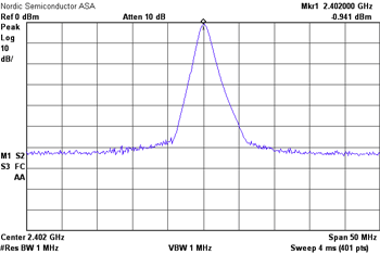
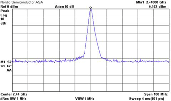
Fundamental
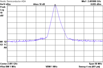
Fundamental Hi
Fundamental Mid
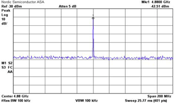
2nd Harmonic
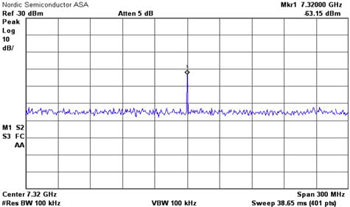
3rd Harmonic
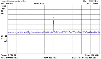
4th Harmonic
Figure 4. Active Measurement Results
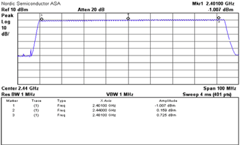
Carrier Sweep
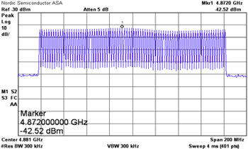
2nd Harmonic Sweep
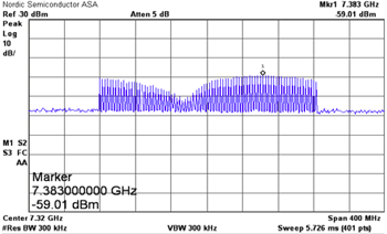
3rd Harmonic Sweep
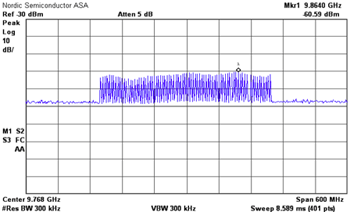
4th Harmonic Sweep
Appendix A