Mini-coupler 900MHz (Extended Frequency) Application Note

Introduction
Johanson Technology introduces P/N 0898CP14C0035001T, a 900MHz directional RF SMD coupler for wireless applications.
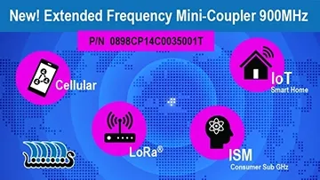
This is a 900MHz directional RF SMD coupler supports a passband frequency range of 865 – 928 MHz, making it ideal for ISM consumer Sub GHz, IoT smart home, cellular, and LoRa® applications. The small size, EIA 0603 surface-mount design, and RoHS compliance ensures easy integration into compact PCB layouts.
General Specifications
- Passband Frequency: 880 - 915 MHz (primary), 865 - 928 MHz (extended)
- Insertion Loss: 0.35 dB Max.
- Return Loss: 18 dB Min.
- Coupling: 17 ± 1.0 dB (primary), 17 ± 1.2 dB (extended)
- Isolation: 30 dB Min.
- Power Capacity: 2 W Max. (CW)
- Operating Temperature: -40 to +85 °C
- Storage Conditions: 45% - 75% RH, +5 to +35 °C, 18 months max for unused T&R product.
Applications
Johanson Technology's Mini Coupler, 0898CP14C0035001T, SMT is suitable for various RF applications, including:
- ISM Consumer Sub GHz: Ideal for industrial, scientific, and medical applications operating in the sub-GHz frequency bands.
- IoT Smart Home: Enhances connectivity for smart home devices by providing reliable coupling and isolation.
- Cellular: Supports cellular communication applications by maintaining signal integrity and minimizing loss.
- LoRa®: Optimized for long-range, low-power communication in IoT networks.
Recommended PCB Layout
For optimal performance, the PCB layout should be designed to match the 50 Ω characteristic impedance, considering the PCB material and thickness. The coupler's terminals should be connected as follows:
- Pin 1: Input
- Pin 2: Main Output
- Pin 3: Termination
- Pin 4: Coupled Output
Refer to the mechanical and land pattern dimensions for precise placement. Request Layout Files
Design Challenges and Solutions
Coupling and Isolation
Achieving precise coupling and isolation in compact designs can be challenging. P/N 0898CP14C0035001T offers 17 dB coupling with ±1.0 dB tolerance and 30 dB isolation, ensuring reliable signal separation and minimal interference.
Insertion Loss
Minimizing insertion loss is crucial for maintaining signal strength. This coupler achieves an insertion loss of 0.35 dB Max, providing efficient signal transmission without significant loss.
Compact Integration
The small EIA 0603 form factor allows for easy integration into space-constrained designs, supporting modern miniaturization trends in electronic devices.
Temperature Stability
Designed to operate within a wide temperature range of -40 to +85 °C, this coupler ensures consistent performance across varying environmental conditions, essential for outdoor and industrial applications. Automotive extended range is available upon request.
Customization Options
Johanson Technology offers customization for the P/N 0898CP14C0035001T coupler to suit specific application needs, including:
- Operational Frequency: Tailored to different frequency bands within the 865 – 928 MHz range.
- Component Size: Alternative sizes for unique PCB layout requirements.
- Application-Specific Adjustments: Enhanced performance characteristics for specific use cases.
Tape and Reel Packaging
Part Number 0898CP14C0035001T is available in T&R packaging, with 4,000 pieces per reel, facilitating automated assembly processes.
Visit Tape & Reel Packaging for detailed packaging information and reel dimensions.
Relevant Resources for RF Designers:
0898CP14C0035001T Product Info Page